


Combustion Air and Flue Liners
The following are comments are from the 2000 Uniform Mechanical Code checklist used by H.V.A.C. installers as well as Local Permit Inspectors. There are other
Code Books being used by other Inspectors also!
The following comments based on the 1997 edition of the Uniform Mechanical Code (UMC) will be
resolved before a permit is issued. This correction list is not a building permit. The approval of plans and specifications does not permit the violation of any section
of the Uniform Mechanical Code or any federal, state or local regulation.
A. General Requirements top____ Provide information on the listing of the equipment installed. (Section 302.1) ____ Provide the manufacturer's installation instructions for the ___________. ____ Unvented or direct fired fuel-burning equipment are only permitted in Group F, S or U Occupancies. (Section 303.1.1) ____ Equipment that is installed in Group S, Division 3, 4 or 5 and Group U, Division 1 Occupancies, and has a flame, generates a spark or uses a glowing ignition source open to the space in which it is installed, shall be elevated so the source of ignition is at least 18 inches (457 mm) above the floor. (Section 308) ____ Appliances installed in garages where they may be subjected to mechanical damage shall be suitably guarded against such damage by being installed behind
protective barriers or by being elevated or located out of the normal path of vehicles. ____ Boilers not listed for closet or alcove installation shall be installed in a room having a volume at least 16 times the total volume of the boiler. Note: When computing the room volume, a maximum height of 8 feet (2438 mm) is allowed. (Section 304.2) ____ The equipment installed outside the building shall be listed for outdoor installations or be in an approved weatherproof enclosure. (Section 304.3) ____ The mechanical plan review and approval cannot be completed until the approved architectural plans showing all of the fire-rated corridor walls, occupancy separation walls and division walls, shaft walls, horizontal exit walls, etc., are submitted for reference use. ____ It should be noted on the plans that each piece of heating, ventilating and air-conditioning equipment shall be labeled to the space served as required by Section 304.5. ____ Show condensate lines on plans and where they will terminate. (Section 310.1)____ Overflow drains from air-conditioning units should discharge to conspicuous locations as required by Sections 310.2 and 1106.12. ____ Show location of heating, cooling and ventilating equipment. ____ Furnish the mechanical equipment schedule identifying the equipment manufacturer's name, model number, capacity, etc. ____ Provide duct layout showing size, duct gage (if metal) and grill (register) locations. ____ All mechanical equipment shall be listed and labeled by an approved agency. If not, complete information on the equipment, including manufacturer's data sheets, test reports, etc., shall be provided to allow for evaluation. Testing by an approved agency will be required before approval is granted. |
B. Heating Equipment top
____ Listed heat-producing equipment shall maintain the required clearances to combustible construction specified in the listing. Devices such as doorstops or limits, closers, drapery ties or guards shall not be used to provide the required clearances. (Section 304.1)
____ A warm-air furnace shall not be located in a room used or designed to be used as a bedroom, bathroom, closet or in any enclosed space with access only through such room or space. (Section 904.5)
____ Vented Wall Furnaces: Shall not be installed closer than 6 inches from an inside corner and located so a door cannot swing to within 12 inches perpendicular to the air inlet or outlet opening. (Section 314.1)
____ Provide a door at least 24 inches (610 mm) wide and large enough to remove the largest appliance in the closet, alcove or basement. (Section 903)
____ Provide a service space of not less than 30 inches (762 mm) deep and the height of the furnace, but not less than 30 inches (762 mm), at the front or service side of the appliance with the door open. (Section 903)
____ Provide a 120-volt receptacle within 25 feet (7620 mm) of and on the same level as the equipment. (Section 309)
____ Provide lighting to all equipment required by the Uniform Mechanical Code to be accessible or readily accessible.
____ Equipment designed to be fixed in position shall be securely fastened in place as required by Section 304.4.
____ Liquefied petroleum gas-burning appliances shall not be installed in a pit or basement. (Section 304.6)
____ Fuel-burning condensing appliances should be provided with condensate drains in compliance with Section 310.
____ Detail of furnace enclosure and blower-type furnace should be shown on the plans. The following provisions should be considered (Section 904):
- The compartment should be at least 12 inches (305 mm) wider than the furnace.
- Furnaces should have a minimum 3 inches (76 mm) working space on sides, back and top.
- Furnaces should have at least 6 inches (152 mm) clearance along the entire front of the fire box.
____ Details of equipment installed in attic shall be shown on the plans. The following provisions should be considered (Section 908):
- Attics shall have an access space large enough to allow the largest piece of equipment to be removed, with a minimum of 22 inches by 30 inches (559 mm by 762 mm).
- Clearances from combustible construction as recommended in the manufacturer's installation instructions shall be maintained.
- Distance from the passageway access to the furnace shall not exceed 20 feet (6096 mm).
- Passageway to the furnace shall be unobstructed and shall have continuous solid flooring not less than 24 inches (610 mm) wide from the access opening to the furnace.
- A level service space at least 30 inches (762 mm) deep and 30 inches (762 mm) wide located at the front or service side of the equipment.
____ Access to equipment on roof should be shown on the plans. When a ladder is provided, the following features should be indicated (Section 910):
- Ladder side railings should extend at least 30 inches (762 mm) above roof edge or parapet wall.
- A 14-inch-wide (356 mm) ladder should be provided with rungs not more than 14 inches (356 mm) on center.
- Ladder should provide 6 inches (152 mm) of toe space.
My H.V.A.C. Professional says I need combustion air ducts installed - why?
D. Combustion Air top
____ Combustion air provisions should be shown on the plans for the fuel-burning equipment. Sizes of openings and/or ducts and their points of termination should be indicated in compliance with Chapter 7.
____ An upper combustion air opening or duct should be provided and located within the upper 12 inches (305 mm) of the enclosure. In addition, a lower combustion air opening or duct should be provided and located within the lower 12 inches (305 mm) of the enclosure. (Section 702)
____ One combustion air opening sized at 1 square inch per 4,000 Btu/h input of the appliance or appliances, but not smaller than the vent flow area, shall be allowed within the upper 12 inches (305 mm) of the enclosure. When this is done, all of the combustion air shall be taken from the outdoors and the appliance shall have a minimum clearance of 1 inch (25 mm) on the sides and back, and 6 inches (152 mm) on the front. (Table 7-1)
____ Upper and lower combustion air ducts should not be joined as shown on the plans, but should be completely separated as required by Section 704.1.6.
____ Upper combustion air ducts should extend horizontally or upward to the outside or to the attic as required by Section 703.1.2.
____ Fire dampers or volume dampers should not be installed in combustion air ducts. (Section 702.2)
____ If an attic is used as a source of combustion air, the following provisions should be indicated on the plans (Section 703.1.2):
- The attic should have at least 30 inches (762 mm) vertical clear height at its maximum point.
- Attic ventilation should be sufficient to provide the required volume of combustion air.
- Combustion air openings should be provided with a galvanized steel sleeve (No. 26 gage) extending 6 inches (152 mm) above the top of the ceiling joists and insulation. Combustion air ducts should also be extended similarly.
- Neither end of upper or lower combustion air ducts should be screened.
____ If an under-floor crawl space is utilized to provide for the combustion air, compliance with the following requirements should be verified (Section 703.2):
- Only the lower combustion air opening or duct should be connected to the under-floor area.
- The under-floor area should have an unobstructed opening(s) to the exterior of at least twice the area of the required air openings.
- The height of the under-floor space should be in compliance with the requirements of the UBC and should be without obstruction to the free flow of air.
____ Combustion air for blower-type furnaces should not be obtained from the same area as the return air (within the building) unless complete compliance with all of the provisions of Section 906.6.5(3) is clearly demonstrated.
____ Combustion air duct sizes should be at least 1 square inch per 2,000 Btu/h (109 mm2/W) per duct, since ducts are not vertical, as required by Table 7-1.
____ Combustion air openings or ducts should be at least 1 square inch per 1,000 Btu/h (2.20 mm2/W) per opening or duct, since combustion air is obtained from the inside of the building, as required by Table 7-1. Note: Minimum of 100 square inches (0.064 m2) for each opening or duct.
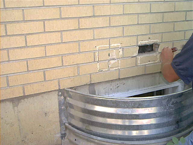
This furnace had no combustion air ducts run to the equipment room. This is a code and is also a VERY UNSAFE condition that MUST be remedied! We will have to knock out (2) 6" square holes in the brick wall above the basement window pictured below.

Below, we have found where the ducts will run in the joist space and have marked the wall. This wall was particularly difficult as each yellow brick was poured with concrete inside each brick. A cement chisel is used to make the rough hole and then it must be finished by chipping to the exact size. Expect to pay more for a wall like this as going through a wooden wall is obviously much easier and less time consuming.
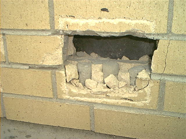
Below is a close up of the interior of the wall. Note the crack to the right of the hole. This happens no matter how careful you are trying to be. The grille will cover this crack however.
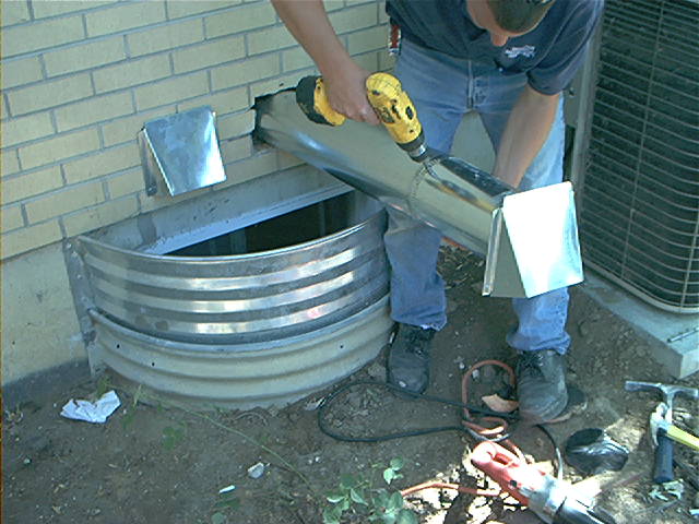
Below we have installed one of the ducts complete with the combustion air grille. The grilles are made for this purpose and are slanted to direct rain water away and have a screened opening to keep unwanted visitors out of the basement. One duct will end up near the furnace and water heater and will be left high at ceiling level. The other duct will be extended to within 12" of the basement floor using elbows. This completed combustion air system installation will supply fresh air to the gas appliances and keep the equipment from making carbon monoxide. Worth noting is the code that says " We need to be further than 10' from our combustion air ducts to a dryer vent ".
E. Vents and Chimneys top
____ The factory-built chimney shall be installed in accordance with the terms of its listing and the manufacturer's installation instructions. (Section 812.1)
____ Provide the manufacturer's installation instructions for the factory-built chimney.
____ Terminate the vent at least 4 feet (1219 mm) from a property line except a public way. (Section 806.6)
____ Terminate the vent on the direct vent appliance, with an input less than 50,000 Btu/h (19 kW), at least 2 feet (610 mm) from a property line except a public way. (Section 806.6, exception)
____ Portions of venting systems that extend through occupied and storage spaces shall be enclosed. (Section 804)
____ A combustion products vent, vent connector, chimney or chimney connector shall not extend into or through an air duct or plenum. (Section 804)
____ Gravity flue vents should not slope more than 60 degrees from the vertical. In addition, the total horizontal run of the vent (less than 45 degrees from horizontal) and the connector should not exceed 75 percent of the vertical height of the vent, as required by Section 805.
____ The gravity flue vent connector should not slope less than 1/4 inch per foot [1/4 unit vertical in 12 units horizontal (2% slope)] as required by Section 805.
____ Gravity flue vent sizes should not be less than the size of the vent collar on the appliance or less than 7 square inches (4516 mm2) [3-inch (76 mm) diameter] as required by Sections 808.
____ Detail of the chimney or vent roof penetration should be provided to ensure compliance with the provisions of Chapter 8.
____ Show the termination of the appliance vents above the roof.
____ Factory-built chimneys for residential fireplaces should terminate at least 3 feet (914 mm) above the roof and 2 feet (610 mm) above any part of the building that is within 10 feet (3048 mm) of the chimney, as required by Table 8-4.
____ The vent for the wall furnace should be a Type BW gas vent. The first ceiling plate above the furnace in a stud cavity enclosing the vent should be ventilated. Each subsequent ceiling plate should be fire stopped by the fire-stop spacers furnished with the vent.
____ When the BW vent extends through an attic in a single-story building, a metal sleeve not less than No. 26 manufacturer's standard gage steel, having the same area as the opening through the ceiling plate, should be extended to a point at least 12 inches (305 mm) above the top of the ceiling plate or 2 inches (51 mm) below the roof sheathing, whichever is the lesser.
____ Type BW gas vents should extend from the header plate to a point above the highest ceiling plate without any offsets or crossovers.
____ A sheet metal barrier should be installed between a Type BW gas vent located in a stud space and wall covering constructed of perforated lath, metal lath or building paper.
____ Type BW wall heater vents should terminate at least 12 feet (3658 mm) above the bottom of the furnace.
Why may I need a Chimney Liner when my Furnace is changed?
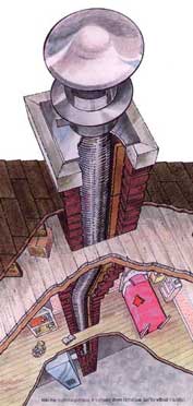
Many times when a new furnace is installed, especially if it is the newest 90% condensing furnaces, your H.V.A.C. professional may want to install a flue liner. These liners are usually flexible stainless steel liners that can be installed in most existing chimneys. Usually they are required on masonry chimneys, but sometimes they are needed even with a metal factory built chimney! There can be many reasons for this. Some of them are -
The existing masonry chimney may be crumbling or otherwise is becoming unsafe or unstable.
By installing higher efficiency furnaces we may be removing too much heat from the existing flue and need to get it to stay hotter for proper drafting of the combustion gases.
Improper flue venting can result in carbon monoxide poisoning, fires and damage to the installed water heater and or furnace. This happens many times when installing a 90% furnace and leaving only a small water heater on a large flue!
The following links and article are excellent sources of education for our clients. After clicking on any of the external links below, please use the back button on your browser to return to our site.
Chimney Safety Institute of America
A national chimney safety organization.
Safe Side Chimney
Thanks to Safe Side for the following information. If you live in the Hartford, CT. area and need chimney services,
please visit their web site!

Gas Flue Lining/Relining |
"But my furnace chimney looks fine on the outside."
Now look inside... See the problems?A look at the inside of this same chimney shows how acid-laden residue from the furnace has attacked this flue. The original clay liner has eroded away; pieces of it
are even missing. (Old chimneys might not even have a liner.) Mortar and bricks are loose and falling, and moisture has leeched through to the home's interior walls. Chimney problems can cause illness and even loss of lives.It's happened thousands of times illness, even death, from carbon monoxide or sulfur dioxide poisoning. With deterioration of the flue, the deadly gases can find their way into your home through even the smallest cracks. In severe cases, the chimney erosion will lead to partial or complete internal collapse, blocking the flue and sending these poisonous gases into the home. But fortunately, the problems of a deteriorating gas or oil furnace flue can be corrected without completely rebuilding your chimney. Revitalize your chimney with a HomeSaver? GasFlexrM Chimney Relining System. HomeSaver will revitalize your chimney. This liner is composed of AL 29-4C stainless steel, a special alloy developed specifically to resist corrosive furnace flue acids.
This liner acts as a barrier between the flue gases and the defects in your chimney walls. What causes water in a gas furnace flue?" The modern, high-efficiency gas furnace is a fabulous engineering marvel. In the old days, low-efficiency gas furnaces sent almost as much heat up the chimney as they put into your home. This pushed your utility bills sky-high and wasted precious natural resources. Today's high-efficiency gas furnaces extract more heat during the burning process and send much less of it up the flue. But for all the benefits these furnaces offer, there's one important side effect that must be dealt with ; excessive moisture in the flue. Some common symptoms of excessive moisture in a gas furnace chimney:
You see, water is a by product of burning. In fact, when you burn 1 cubic foot of gas, you create 2 cubic feet of water vapor. Those old, inefficient furnaces sent so much
heat up the flue that the water created in the combustion process stayed in the form of hot steam all the way up and out the chimney. "What problems result from sulfur compounds in an oil furnace?"While we commonly think of a masonry chimney as a permanent structure, practically impervious to damage, that's not the case. Without a proper liner and annual maintenance,
the toll can be a heavy one.
When the oil you heat with is burned, a sulfur soot is formed on the inner wall of your chimney. This sulfur-laden soot combines with moisture in the flue, a natural
byproduct of today's highly efficient furnaces. This forms an acid mixture which attacks your chimney, eroding your flue tiles and mortar joints. This leaves dangerous
voids and allows the sulfuric acid mixture to attack the brickwork, your last line of defense against deadly sulfur dioxide and carbon monoxide poisoning. Additional
danger exists as the chimney debris, or silt, falls to the bottom of your chimney. This can eventually plug the chimney, allowing dangerous gases to enter your home. |
 Many chimneys venting gas or oil furnaces
may appear to be in fine condition on the outside. But inside it could be a completely different situation. Yesterday's chimneys were not designed for venting today's
more energy efficient furnaces. Let's take a close look at what really counts. the inside.
Many chimneys venting gas or oil furnaces
may appear to be in fine condition on the outside. But inside it could be a completely different situation. Yesterday's chimneys were not designed for venting today's
more energy efficient furnaces. Let's take a close look at what really counts. the inside.Copyright 2000 Safeside Chimney and Duct Cleaning. All Rights Reserved.
